Random Projects and Comments

FPGA Development Setup

Published on February 9, 2015, by in FPGA.

MachXO2 Eval Board
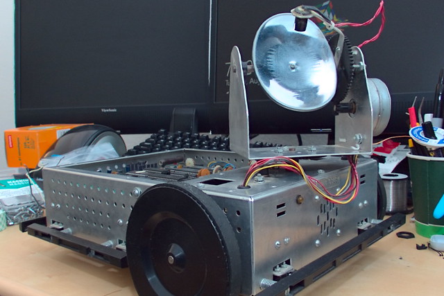
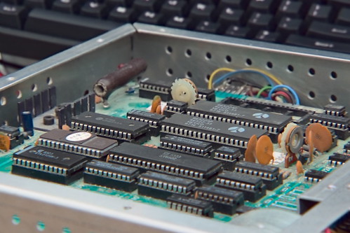
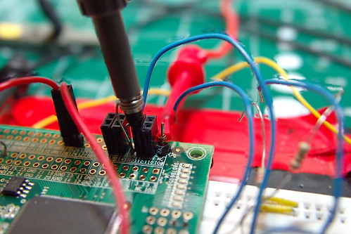
The development board I chose for this project is the Lattice MachOX2 board. (P/N: LCMXO2-7000HE-B-EVN )   Its a very simple board, cheap, and easily obtainable from a supplier I already use.  It doesn’t have a lot on the board, the MachOX2 has an internal oscillator, core voltage regulator, and configuration flash both of which they take advantage of on the eval board.   All that they need to get the chip up and running is an IO voltage regulator (3.3v in this case) and a FTDI chip for programming.  They also include 8 LEDs for debugging and the proverbial ‘blink’ example.

MachXO2 Eval Board - XTAL
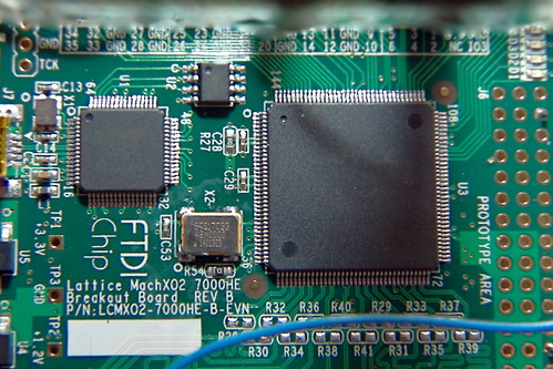
Even though the MachOX2 has an internal oscillator there is a7.0mm x 5.0mm 4-SMD footprint for a oscillator which routes to pin 27 at a 3.3v logic level.  From what I could figure out the internal oscillator couldn’t be routed on a primary clock path, so I fitted a 48mhz oscillator to the board.   I was likely to need an external clock anyways since the internal one may not be stable enough for the high speed serialization.

MachXO2 Eval Board - IO Voltage
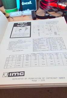
Another modification I made to the board was to change one of the IO supply voltages.  The default configuration is that all of the IO banks are fed with 3.3v across a 1 ohm resistor.  There are two advantages to this, by measuring  the voltage drop across that resistor you can determine the current you’ll need if you move your design to a custom PCB.  The second being by removing that resistor you can feed a different IO voltage to any bank you like ( or just a higher current supply if necessary).  Details of the power measurement and modifications are on page 15 of the breakout board’s user guide linked below.

For the software I went with the Lattice Diamond package.  There is another option from lattice called ispLEVER which I havn’t tried at all so I can say anything about it.   I did have an issue with the 64-bit version of Diamond reconising the FTDI JTAG interface on the eval board.  I didn’t have this problem on the 32-bit version of the software so that is what I’m using for now.

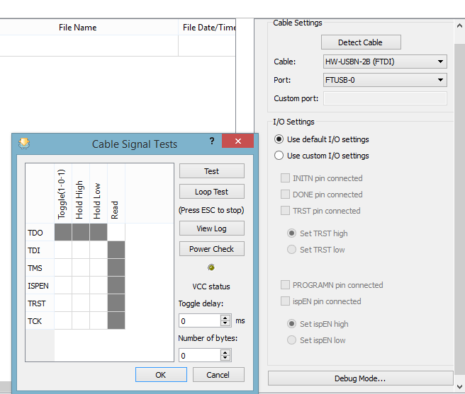
eeWiki has done a great tutorial on using Lattice Diamond for the first time so I don’t duplicate those steps here.  Another option is the demo code provided by Lattice for the Breakout Board.  Its available from the MachOX2 Breakout Board site under ‘Downloadable IP’.  They do essentially the same thing main difference is that the eeWiki one is VHDL where as the Lattice one is Verilog.  It seems that much of the Lattice examples and documents prefer Verilog so I followed the eeWiki for setting up the environment but used the Verilog files from Lattice.  Since I had some issues getting the FTDI drivers to work correctly I would add its a good idea to check that you can talk to your programmer early in the process.  To do that open up the programming window, and tell it what cable you have.

ProgrammingScreen

If you haven’t synthesized your design yet, you will get an error, but that’s ok.  The error you’ll get is “ERROR – JEDEC file cannot be found.”  If you see anything about the FTDI chip not responding you may have a driver/communication problem.  There is a nice way to check this, after acknowledging the error yo will have a ‘Cable Settings’ window on the right side.  The ‘Debug Mode’ button will give you a debug tool to run tests on the cable.   When you click the test buttons the light above ‘VCC status’ will change to Green ( test passed ) or Red ( test failed ).   If a test fails the error message will be in the output window.

ProgrammingDebug


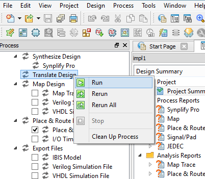
There is a one other stumbling block that I ran into initially. Which was all the different steps in building the output file.  One thing is that if you have not synthesized your design yet you will not be able to connect your pins to anything.  The software doesn’t compute which wires are available for connecting until after your code is synthesized and translated.  To accomplish this goto the process pane, double click or right click on Translate design to run.  You need to do this anytime you made changes to the code adding/removing wires, especially if they are connected to pins.

Run

Links:

MachOX2 Breakout Board Site

MachXO2 Breakout Board Evaluation Kit User Guide

eewiki Lattice Diamond Tutorial


New Project – Scorpion/OpenCV

Scorpion Side
I’ve had this Scorpion robot platform for a long time.  It was given to me by my uncle in the early to mid 1990’s is my best guess.  The kit was made by Rhino Robots in 1984.  From what I can tell they are still around though do not produce the Scorpion anymore.

Scorpion Orginal Board
The Scorpion was built around a Motorola 6502 controller, with the motor control offloaded to dedicated stepper drivers.  Since it was designed from the beginning to be a research tool, the motors, bumpers, lights, and sensors are completely separate from the processor board.  For this reason its very easy to add whatever processor board you want.  In the past I’ve built boards from some of the early Atmel 8-bit processors ( the AT90S1200 comes to mind ).  Later on I had an arduino board.

ManualManual- DatasheetManual - Code

Since this was developed long before the internet was common place everything is in there.  Datasheets, code, lengthy descriptions on how every system interacts.  I don’t know of any manuals that even comes close to the detail in the Scorpion’s manual.

ScorpianEyes

Recently I got introduced to the OpenCV project by a fellow member of Makers in Manchester and needed a platform to play with it on.  To that end I decided I should be able to adapt the Scorpion to work well with that.   I’ve already fitted some cameras to the spot where it originally had a single CdS cell for ‘image’ sensing.  The plan for processing is to run the cameras and vision and control through a Raspberry Pi and an atmega 1284p for the motor control.   Ultimately I would like to build a single board system though, more like the original robot used.  Would make a good project to learn how to design boards around the ARM chips I would likely need for the OpenCV system, and possibly intregrate the motor control onto that same chip.


Catchup

I neglected to really document the last few projects I have done.  Mostly out laziness but also I didn’t really feel they were all that interesting, basically just re packaging of existing tech/ideas into something useful for me.  You can find them on my thingiverse and G+.

SMD Component Dispenser: http://www.thingiverse.com/thing:394354

Ham Radio Go-Box: https://plus.google.com/+RyanSuttonRMS/posts/Us3UmvWJAME

New, better documented project coming soon!


Breakout Board for the Toshiba TB62212FNG

Published on June 19, 2014, by in Uncategorized.

Needed a bunch of H-Bridges for a project that I likely won’t move forward with, but I found this chip that has 4 H-Bridges in a really small package. It only comes in surface mount packages so I threw together a breakout board for the HTSSOP-48 version. Schematic and eagles files can be found here.


Sanguino for Arduino >1.0 Release


Put together a full release of Sanguino that supports version 1.0.1.  Actually ended up not being as difficult as I expected since most of the directory layout has stayed the same.  I was hoping to use the new ‘variants’ to avoid making changes to the core files but ended up needing to do that to get some stuff working.Like I have said before the new method the Arduino team is using to guide the precompiler for different chips by using whether registers exist or not is much better and makes porting it to different hardware much easier.  Unfortunately the few libraries I have has issues with did not follow this lead.

The SDcard lib which is included with the install now has pin assignments hard coded for different processors rather then referencing the core/variant.  It is a quick workaround if you want to use Sanguino (with a atmega1284) with this libary.  Simply change line 120 of ‘arduino-1.0.1/libraries/SD/utility/Sd2PinMap.h’ from

#elif defined(__AVR_ATmega644P__) ||  defined(__AVR_ATmega644__)

to this

#elif defined(__AVR_ATmega644P__) || defined(__AVR_ATmega644__) || defined(__AVR_ATmega1284P__)

I was able to get my DataLogger project up and running with a fresh bootloader burn and recompiled in 1.0.1.  The project uses SPI, I2C, ADC, and both UARTS so I generally use it as a test case since it covers the most common features used.  I did have to modify my GPX, and Producer/Consumer libraries to work with 1.0 which was fairly easy. Mostly just changing WProgram.h to Arduino.h in a few places as well as some string functions which changed.  I’m going to clean those up and post them soon hopefully.

You can grab the new version over on Google Code: http://code.google.com/p/sanguino/downloads/detail?name=Sanguino-0101r1.zip


Sanguino for Arduino >1.0

Published on July 15, 2012, by in Arduino, Software.

After putting it off long enough I started working on updating Sanguino to work with Arduino 1.0 and higher.   It looks like this could actually be easier then any version since. It looks like the Arduino guys are now doing all core features based on register values.   I first saw this tactic from msproul at http://www.avr-developers.com/ and used the same method whenever possible when I was modifying the core for Sanguino.

I haven’t really done any extensive testing but I was able to get blink, SPI, and UART functions working by just adding a ‘variant’ to the original core.  This brings up an interesting delema, which is how to install Sanguino.  If I stick with it as just a ‘variant’ (which I would really like to do) I need to be able to install into the variant directory which isn’t a big deal, but also append to the board.txt. This is no longer as simple as unzipping an archive into a directory, the boards.txt step would have to be manual or some sort of setup routine run. Not to mention making all of that cross platform.  I need to dig deeper but I’m guessing that using things like extra interrupts or UARTs might require actually modifying the core which will make my decision for me.  The traditional approach of adding a completely new directory under hardware is an option but I want to make that a last resort.

(more…)


New Sanquino Version 0023R4

Published on June 23, 2012, by in Arduino, Software.

The last few months has been busy for me, but I’m finally getting time to put back into electronics.  I had found that INT2 was not accessible with the previous Sanquino core I had built so after fixing that as well as a couple other bugs others had pointed out I put together a quick release.  As I say on the Google Code site, this will probably be the last release for Arduino 0023.  I am going to start putting my time into getting the bootloaders/cores working with Arduino 1.0 ( If possible)  I do not want to go the route of a fully forked arduino environment.  There is not necessarily anything wrong with that but I like the idea of a plugin much better and hopefully we can keep that alive.

Download the new version HERE


GPS Logger Hardware v5.0

Published on March 20, 2012, by in Hardware.

DSCN0933
Got another rev of the Skiing Datalogger, I had REV:B boards made but never built one up since I knew of the issue with the gyro and the holes didn’t line up with the case. This board is REV:C which I added some holes, all the flying wires are gone (so far) except the rework of the Venus GPS module which Sparkfun has changed in their new version. I have tested the individual components. Only the accelerometer is giving me issues at the moment. It is doing the same thing as the 6dof board though so it could be something in my code.
Datalogger Front Panel v1
I also had a board to be used as a front panel made, mainly to give a better way to connect to the remote keypad but it also serves as a place to LEDs and switches. The LEDs are bottom entry mounted on the back of the panel. Switches being surface mount on the front. (more…)


Sanguino Dev Enviroment

Published on March 4, 2012, by in Arduino, Software.

Should have posted about this earlier. I have been updating the Sanguino project over on Google Code with the changes I have made to support the atmega1284P and support up to arduino 0023.  If you have issues with the HEX files I posted here earlier check out the new versions.  If you still have problems open an issue on google code, I try to go through the issues reported ever week or two.


New Datalogger User Interface

Published on February 4, 2012, by in Hardware.


Previously I have used this interface sewn into a glove to start new tracks in the GPX file and also give me a visual indication that the device is logging data.  The main problem with this system is I can not come up with a good way of disconnecting the glove from the wire to the base unit making taking the jacket and gloves on and off a challenge.   It happens that Sparkfun has a nice ‘wearable keypad’ that I decided to use.  The keypad has a 4-way directional switch, a center switch, and a LED which lights it up.  All the switches and LED reference a single ground pin which is the same method I used for the glove interface so this was a drop in replacement.

Rather then attaching the keypad to the glove again I opted to attach it to the jacket, which should take care of the issue around removing and putting on the jacket.  I also did not want to sew it onto the jacket just yet, so I just pushed some wire through the excess rubber around the keypad making some loops that the strap in the jacket can pass through.

Hoping to try this setup out tomorrow, and collect some more data.

 
credit
© Ryan M Sutton, 2015