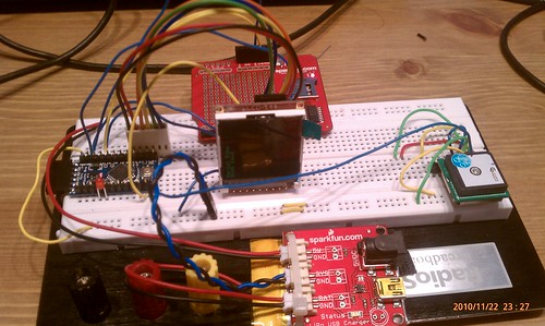
So my next step in my GPS logger project will be to pull the components off the breadboard and build a small prototype to gather some more real world data without needing to be so careful with it. So I figured I would take some time to describe the general layout of the current board.
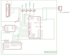
Right now the system is based around an arduino mini pro 3.3v w/ the atmega328 chip. Yes I know those headers are not technically installed correctly but I like this method for prototyping since it allows for a lower profile when mounted and access to test points when in circuit.
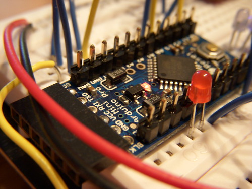
The 3.3v system was chosen mainly for the direct compatibility with microSD cards.
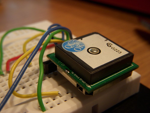
Branching out from that I chose a SUP500F GPS module, I chose this particular receiver for the 3.3v operating voltage, 10hz refresh, and large number of channels. Initially I was a bit scared from some of the reviews out there, but I can say that I have not seen many of the problems which have been reported. Also I am guessing at least a percentage of the ‘DOA’ issues could be resulting to hooking the device up to 5v logic and frying the ports.
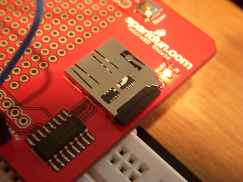
The next major component is the microSD card. I am using the microSD shield from SparkFun. The only reason I am using this for my prototype is my plan is to mount the arduino, and GPS modules onto the small protoboard which should help keep the size down. If I ever do build a board for this I plan to directly mount a [micro]SD card holder onto the board.
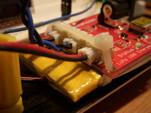
The last required piece of my setup is the power supply. I have a LiPo charger and 1000ma battery which gives me plenty of power while still being able to be crammed into a small project enclosure.
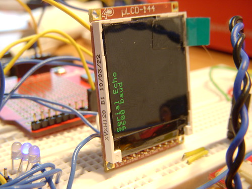
I also added a small LCD screen for debugging, since I’m only using the RX pin on the NewSoftSerial port for the GPS I use the TX pin to talk to the LCD. Doing this keeps the hardware UART for debug messages for the time being. In my infinite wisdom I decided when I got the LCD display that it should have a right angle header on it rather then the strait header it came with. I am regretting that decision but do not really want to rework the display again.
So as for operation, the device will log into a single GPX track as long as pin D7 is pulled low, this state is verified by lighting the LED on D4. Once the GPS has a valid 2D fix it will start writing TRACKSEGs at 1hz. The LED on D3 blinks each time this happens. Once D7 goes high the GPX is closed. If at any point the error handler is called (usually a SD error) the sketch stops and the LED on D2 is turned on.
The next steps will be to add some more switches to close and start new tracks and like I said shrink it down a bit to cram it into an enclosure to start pulling piles of data. So stay tuned.